Introduction to XREFs
The bulk of time spent in AutoCAD is in the workspace, creating geometry, annotating it, and finding ways to accurately communicate intent. However, the beauty of digital drafting is that content can – and should be – reused, often. This is where XREF’s come in. An XREF (External Reference) is just what its name suggests – a reference to an external file, whether a drawing, an image, or a data file. If additional questions arise or you would like a more comprehensive training course on CAD procedures, ARY Engineering can be reached at 509-491-7865, or [email protected].
Benefits of using XREFs?

First, the risk of accidentally modifying the original source geometry is reduced, since the user is no longer working within the source file but is instead referencing it. Next, the file size of AutoCAD drawings that use XREFs is approximately 10x smaller than that of drawings that instead use the original geometry. For example, if a site plan’s geometry is copied into a blank file, the file’s size is 20 MB. However, if that same geometry is kept in an isolated file, and then referenced into a blank file to be used as a background, the file size is now approximately 2 MB.
Additionally, if a source file is modified, the changes will be propagated across all files that reference it. This means that should the site plan need adjustment, the changes need to be completed in only one file, as opposed to every instance of the geometry needing adjustment. ARY’s “Untangling a Site Plan” demonstrates the benefits of properly using External References, turning the cleanup and documentation of complex site plans into a straightforward process.
How do XREF’s work?
Let us use a residential development as an example. An initial site plan is created, containing property boundaries, existing infrastructure, terrain data, and additional content that needs to be considered when arranging the residential blocks and parcels. This will be considered the “source” file since it is the source of our data. Good practice dictates that original source files like this should be kept as pristine and untouched as possible, to avoid the possibility of accidentally modifying any original ground data provided by the surveying team. Instead of drafting the concepts on top of the existing data, the concepts will be sketched in a new blank document, with the site plan “source” file referenced.
To implement an XREF in a drawing, use the steps listed below:
- Click Insert tab > Reference panel > Attach
- Alternatively, you can type in XREF
- In the Select Reference File dialog box, open the file you want to attach or overlay.
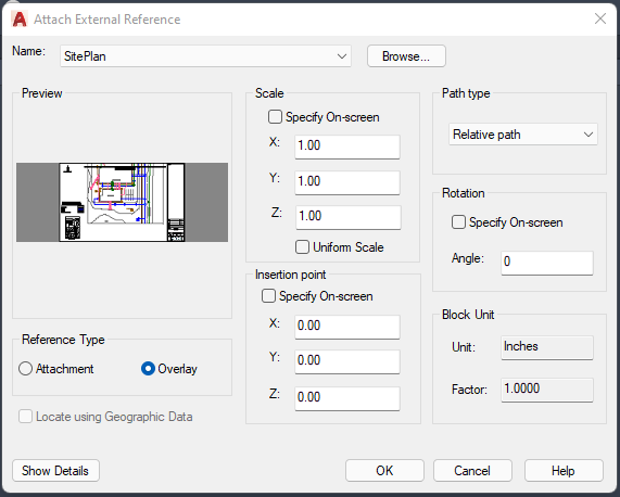
- In the Attach External Reference dialog box, select one of the following for Reference Type:
- Attachment: Saves a copy of the XREF source drawing in your host drawing.
- Overlay: Creates a link to the XREF source drawing in your host drawing.
- Specify the insertion point, scale, and rotation angle; or click Specify On-screen to use the cursor.
- Click OK, and, if necessary, specify the insertion point, scale, or rotation angle in the drawing.
Attach vs Overlay
The most misunderstood and misused option differentiator in CAD is the distinction between attaching vs overlaying an XREF. If a source file is attached to a host file, the source file becomes a veritable part of the host file. If another user then references my host file, they will see all XREFs that are attached to it. However, if an XREF is simply overlayed onto a host file, then it will not appear when other users are referencing the host file.
For example, if a surveying team is defining the site plan for their engineers to use, they would reference their raw survey data as they make the site plan for the entire company to use. However, the engineers working on the development do not need to see the original survey data. In fact, it would clutter up the drawing, making it messy and challenging to work in. Therefore, the surveyors would use the overlay option, which allows them to use their survey source file in the site plan they are creating but will not show up when the engineering team references the site plan.
External References Palette
Once an XREF is added to a drawing, it can be managed through the External References palette. This palette can be accessed through the same steps used to initiate the XREF – through keyboard commands, or the Insert tab in the ribbon. The following data is then displayed in the palette:
| Reference Name | Displays the file reference name. This property can be edited only if single file references are selected. The reference name shows *Varies* if multiple file references are selected. This property is editable for all the file references. |
| Status | Shows whether the file reference is loaded, unloaded, or not found. This property cannot be edited. |
| Size | Shows the file size of the selected file reference. The size is not displayed for file references that are unloaded or not found. This property cannot be edited. |
| Type | Indicates whether the file reference is an attachment or overlay, the type of image file, a DWF/DWFx underlay, DGN underlay, PDF underlay, or an NWD/NWC coordination model. This property cannot be edited. However, if the file reference is a DWG XREF, the Attach or Overlay property can be toggled. |
| Date | Displays the last date the file reference was modified. This date is not displayed if the file reference is unloaded or not found. This property cannot be edited. |
| Found At | Displays the absolute path of the selected file reference. This property cannot be edited. |
| Saved Path | Displays the save location of the selected file reference. This is where the referenced file is saved and is not necessarily the same as the Found At location. Clicking the Open button displays the Open dialog box where you can select a different path or file name. You can also type directly into the path field. These changes are stored to the Saved Path property if the new path is valid. |
Managing XREF Paths
The saved path used to locate the XREF can be a relative (partially specified) path, the full path, or no path. The default path type is relative. Use the REFPATHTYPE system variable to change the default path type. If the host drawing is not saved yet, the saved path column displays a full path with an asterisk prefix to indicate that a change will take place after the host drawing is saved. Before the file is saved, a new read-only property called pending relative path is added to the Details pane of the Xref palette. When the file is saved, the pending relative path property is removed.
Detaching Referenced Drawings
To completely remove an XREF from the drawing, detach it, rather than erase it. Using the Detach option removes the XREFs and all associated information such as layer definitions. If there are nested XREFs in the host drawing, the XREF that it is nested in will need to be opened, and the file will need to be detached from there instead of trying to detach it from the host drawing. Use the Tree View control in the upper-right side of the External References palette to see how XREFs are nested within each other.
Conclusion
Although the primary function of drafting software such as AutoCAD is to create, edit, and annotate geometry, a major function that improves the process is the ability to reuse geometry through the External References option. This allows users to reference, or “point to” existing geometry from within their host drawing, as opposed to recreating the geometry in every file that could be useful. This tool streamlines the drafting process, drastically reduces drawing size and allows for seamless team integration when used properly.
Stuck with a messy tangle of nested XREFs? Need assistance cleaning up and correcting missing links? Would you like further training opportunities for AutoCAD and its tools? ARY Engineering can help! Reach out to us at 509-491-7865, or [email protected].